.png)
Member Cross Section Orientation (beta angle)
The angle defines the member orientation and affects the direction of normal to member loads (N and M loads). The angle can be thought of as how the member is orientated about its own axis. If any member in space is thought to be initially positioned on the X axis, then in order to position the member in the correct position in space it is firstly rotated horizontally, i.e. the α (alpha) angle. Secondly it is rotated vertically, i.e. the γ (gamma) angle to achieve the final position. The β (beta) angle can be seen to perform the final rotation of the member about the axis running along the member length.
With the member in the initial X axis position, a β Angle of zero can be thought of orientating the member to bend vertically about its stronger major axis (xx axis). The sign convention of the β Angle rotation is best understood by placing your eye looking form the member’s smaller node number towards the larger node number, then a positive rotation occurs in the anticlockwise direction.
As with the section properties, initially all members are assumed to have no definite β angle value applied to them and therefore assume a default value of zero.
In plane frames and grillages, the default value of zero causes all members to bend about their major axis only.
In plane frames and grillages, you can only use β values of 0, 90, 180 and 270 degrees.
From the Properties menu you can select the Member Cross Section Orientation (β angle) option. If you are currently in either the Member Loading or Member Section Properties area you can shortcut to the Member Orientation by clicking on the ![]() button at the top right of the screen.
button at the top right of the screen.
Note that this attribute can also be edited in the Member Property Editor.
As with the Member Sections and Materials you can switch between Member ![]() , Global
, Global ![]() and Copy To
and Copy To ![]() modes.
modes.
Member Mode
Member Mode is the default mode and perhaps the mode that you will use most frequently.
.png)
In Member mode you can apply and edit β angles on a member-by-member basis. To do this,
1.Ensure that the ‘Incremental β value change on member click’ is set to zero
.png)
2.Select the member you want to apply or change the angle on. You can select a member by,
a)clicking on it in the main frame geometry area, or
b)if you know the member number you wish to edit then you enter the number in the .png)
c)by selecting the member number from the .png)
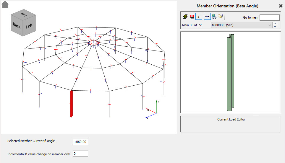
The selected member is highlighted in 3D member profile in the frame geometry window. For this reason, it is recommended not to turn on the global 3D member profile option from the top tool bar while working in this area.
1.Edit the value in the ‘Selected Member Current β angle’ text box to change the angle. As you do this both the selected member in the frame geometry area and the selected member graphics window will graphically indicate the new member orientation.
All changes made affect the current selected member only.
When you select a member in member mode, the current angle of that member is displayed in the ‘Selected Member Current angle’ text box. The member mode can be used to investigate the current angles on members.
While in member mode the ‘Incremental β value change on member click’ option can also be used to change a member’s angle. By entering a value in this text box, then clicking on a member, the member will be rotated by this value. Repeated clicks on the same member will continue to increment its β angle by the entered amount. Again, all changes are shown graphically as the changes are made.
Global Mode
Global mode is used only to change existing angles and cannot be used to apply β angles where none are defined.
.png)
Global mode is used to change the angle on a group of members that have the same angle applied. In other words, global mode can be used to change all occurrences of the same angle at once.
Global mode groups members together that have the same angle. Beneath the global mode icon, the drop list indicates how many different member groups have been created, i.e. how many different angles are currently applied in the frame.
To change β angles while in global mode,
1.Click on the ![]() icon to switch to Global mode.
icon to switch to Global mode.
2.Select the existing angle, i.e. member group you wish to change. You can do this by,
a)Selecting a group from the drop list .png)
b)Clicking on a member in the frame geometry area will move to the member angle group associated with that member.
The members in the group are highlighted in red on the screen, i.e. the highlighted members all have the same angle.
3.Change the β angle for the selected group using the .png)
As in member mode the changes are applied automatically to all members in the currently selected group. Once you are finished in Global mode it is recommended that you return to the Member mode.
Copy To Mode
This is one of the most powerful editing modes, which is used for copying a single angle to a member or group of members in one operation.
.png)
The key concept in Copy To mode is that the value in the box
.png)
To use the Copy To mode,
1.Click on the ![]() icon to switch to Copy To mode.
icon to switch to Copy To mode.
2.Set up the required angle in the .png)
3.Paste this information onto the frame by selecting member(s) in the frame geometry area. You can select member(s) by,
a)Clicking on individual members.
b)Windowing a group of members
When you select members the ‘current value’ is applied to the members in black and removed from members in red. Hence the Copy To can be used to add and remove angles.
Copy To mode can continue to be used by repeating steps1 and 2.
Important Note: Bear in mind that when you are in Copy To mode that when you select a member you have changed the angle of that member. It is vitally important to be aware which editing mode you are in, since haphazardly selecting members while in Copy To mode could disrupt your model. Remember that in Member and Global modes, changes are made as you edit. In Copy mode changes are only made when you click or select members in the frame geometry area.
Tip! When you are finished using Copy To, move back to Member mode. Member mode is safer in that when you select a member you are not changing anything by doing so.